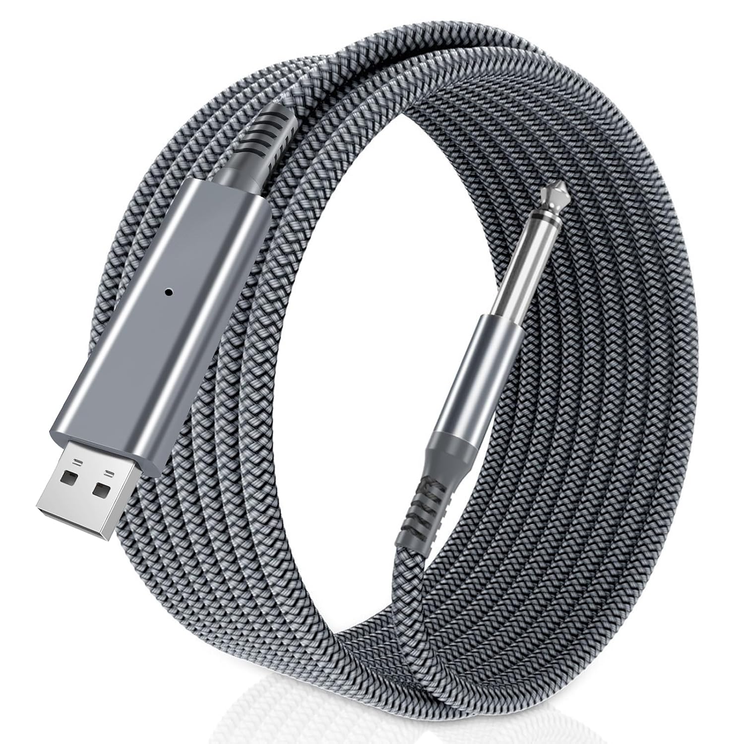
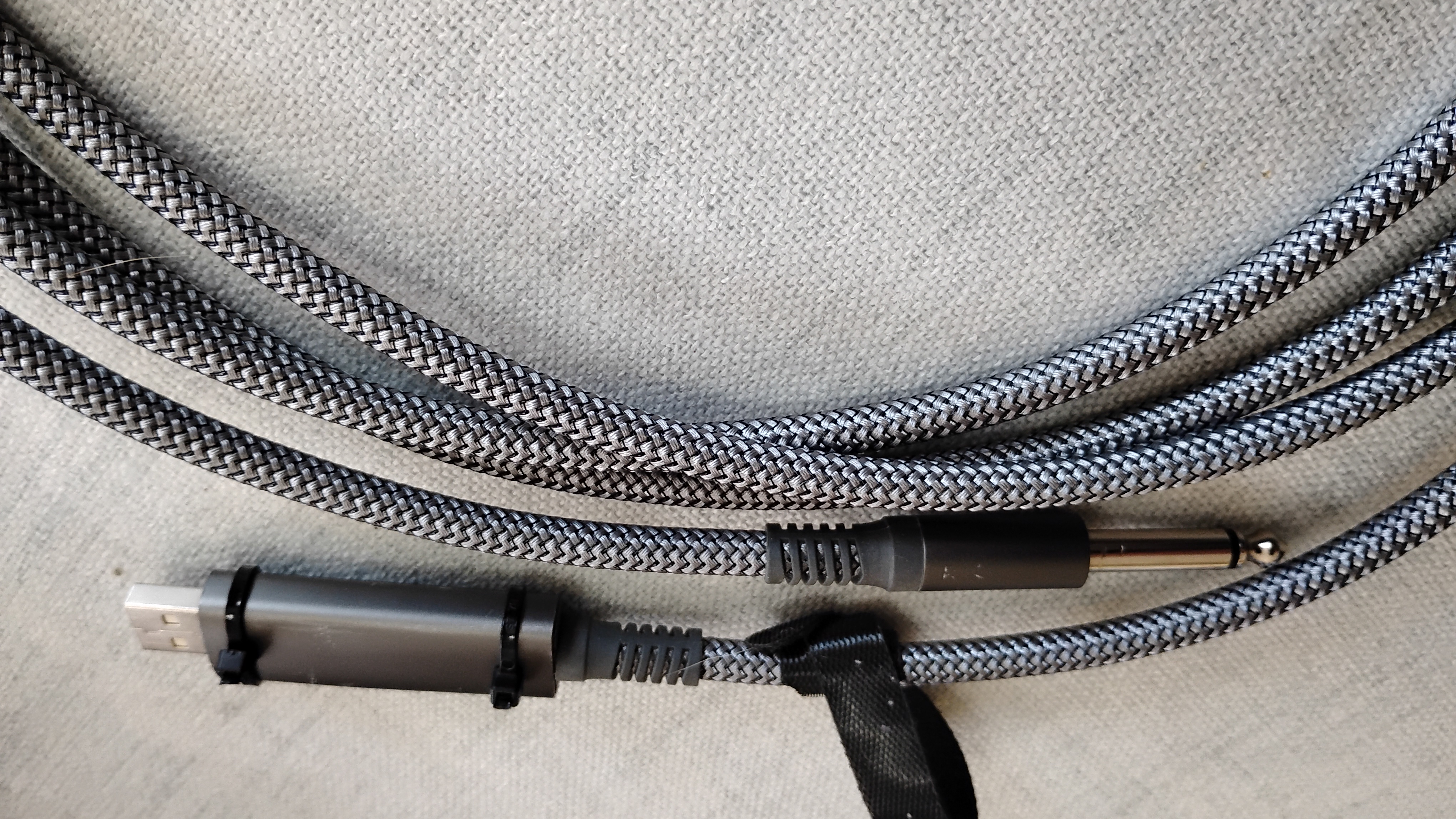
I thought it would be really nice if I could practice on my guitar without a lot of setup of cables and boxes and stuff. I had heard of 1/4 inch jack to USB cables that would allow one to plug direct into their computer. My computer is not exactly a great sounding guitar amp but with software and headphones, it might be alright. Heres what I got:
Problems
Solutions?
- The chip used (C-Media HS-100B) is designed to be used as a mic + headphones USB dongle. It has an output section. The computer thinks that because this is a new device the user has plugged in, it should now be the default output. However, there is no output so no sound.
- My guitar volume control sounds scratchy when I change it. Works fine with an amp. On a hunch, I got out my VOM and found 3vdc on the guitar plug.... Sigh. The company That made the cable was using circuitry made for a computer mic.
Well the first problem is just not going to completely go away but at least on Linux, which I happen to use, I can change the profile for the device to just an input and so the output never shows up. Good enough.
The second problem was going to be a little harder to deal with and as it turns out, was going to show up a third problem. That is what the rest of this story is about.
First I checked the chip information on my computer and got: 0d8c:0014
Then I looked that up and the first four digets are the manufacture: C-Media and the second is the chip or model. With these simple designs the model and the chip are interchangable because there is no extra rom/prom/eprom. I found a blog entry about a similar device with the same code and they had opened theirs and could read the chip inside. It is a c-media HS-100B. So I downloaded the specifications sheet.... which didn't tell me much but I was able to find application notes which has an example mic input circuit drawing. I could see from the picture in the blog that they had copied the circuit in the application notes exactly even using the same componant numbers.
Here is the circuit
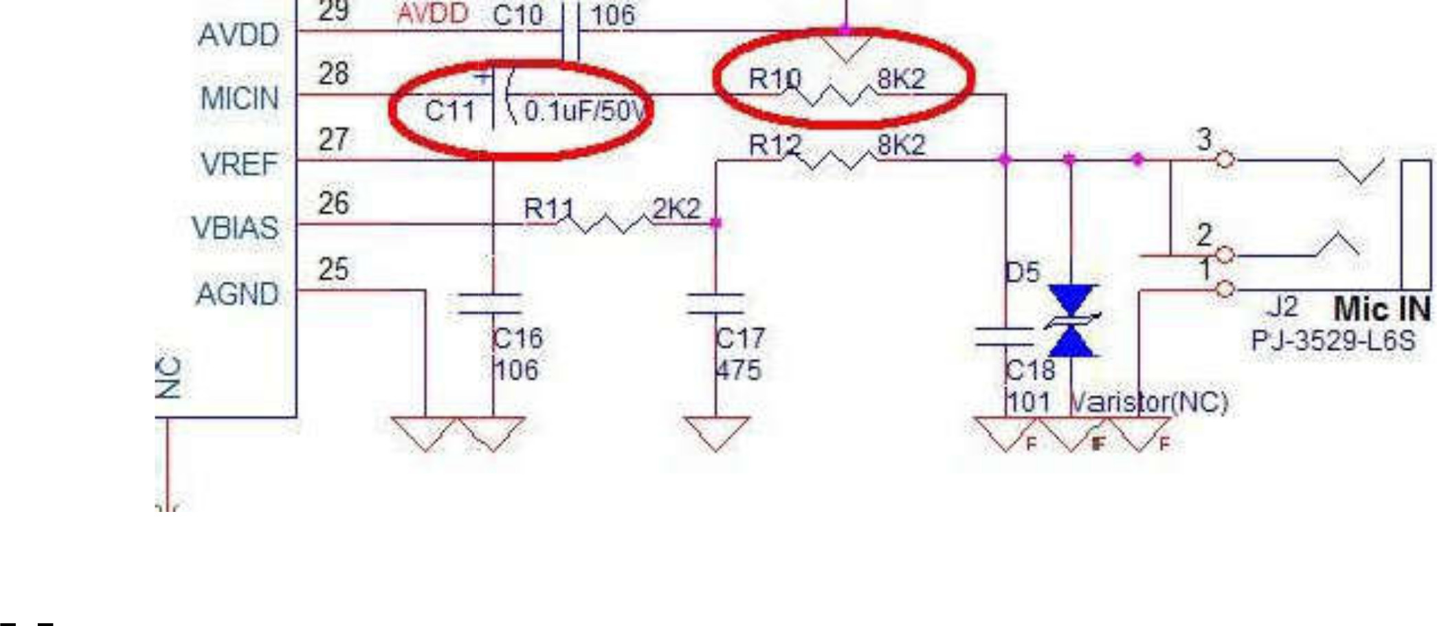
Oh my! This is not good at all. There are two problems here.
- The first is what we knew, vbias is being fed to the instrument.
- The second is how. R12 at 8.2k ohms effectively makes the input impedance 8.2k ohms. This will load down the pickups in the guitar which expect something around 1m ohm or more. C17 makes the other end of R12 ground for AC.
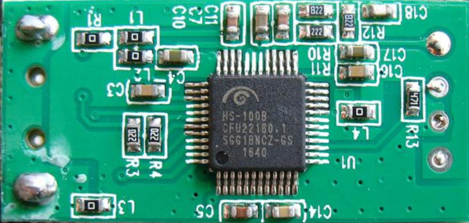
We can see that the pc board above follows this circuit exactly even to using the same numbering for the components. They are all easy to find.
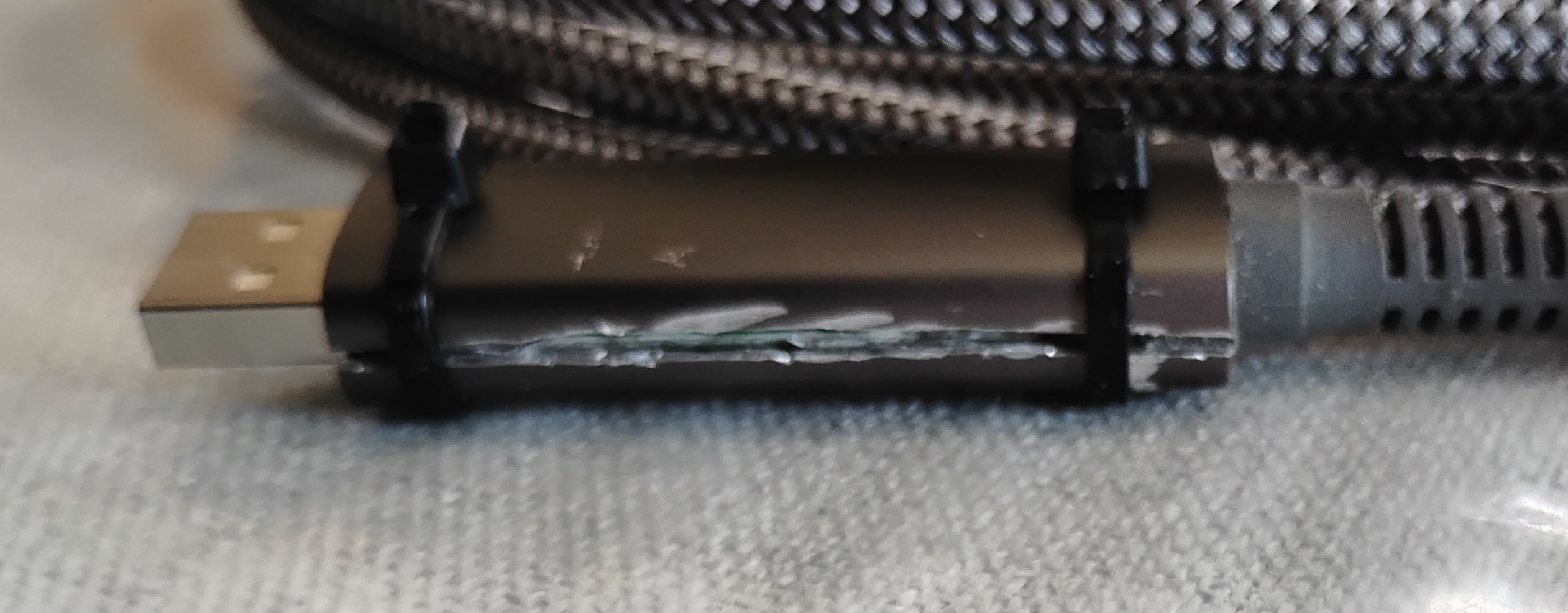
So I cut the shell of my new interface open with a dremmel.
What I found inside was the same chip but my board did not use the same component numbers. It was going to be less easy than I hoped.
Hang on, I haven't told you what I intended. Very simple. I will simply remove R12. This will:
- Remove the bias voltage from my guitar
- Increase the input impedance by at least double but likely more.
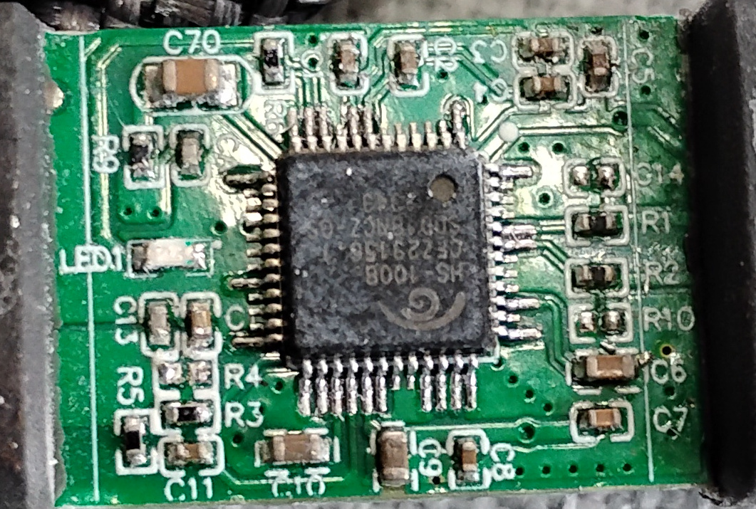
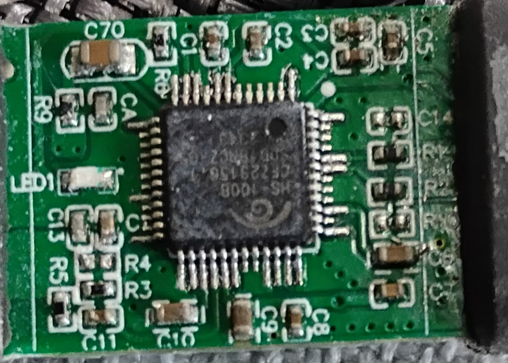
What I saw on opening.
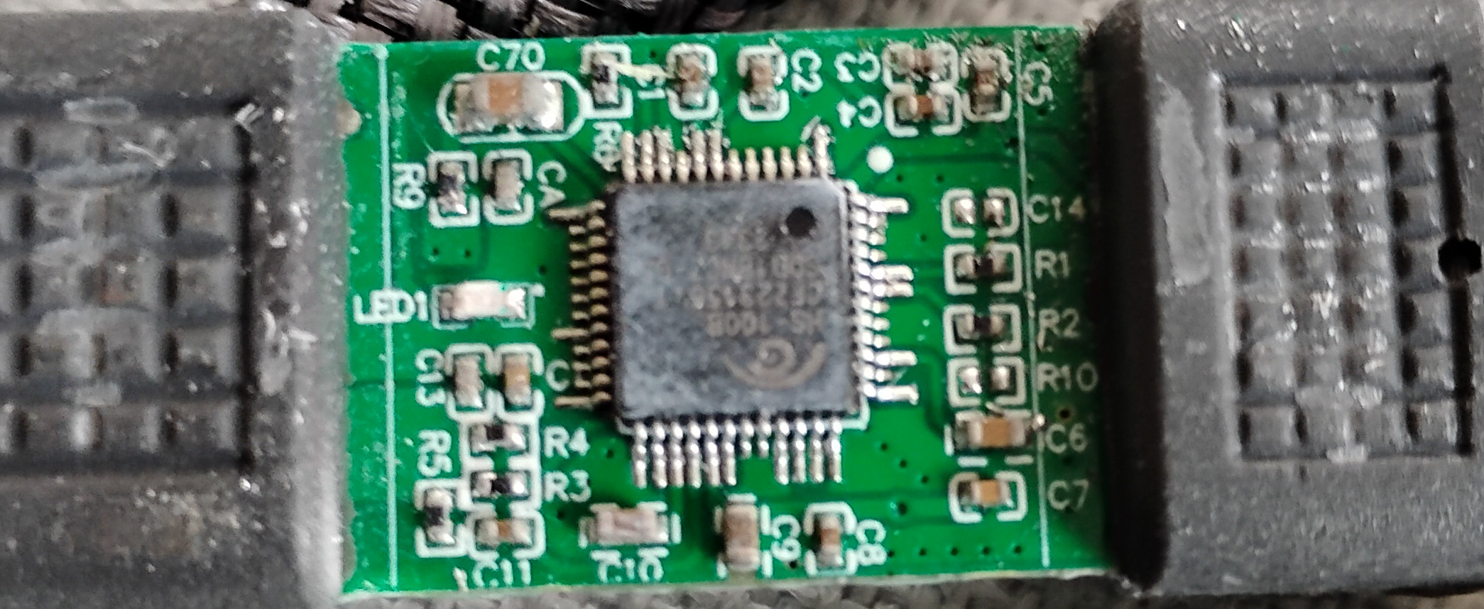
Lets expand the corner of the image we want to look at
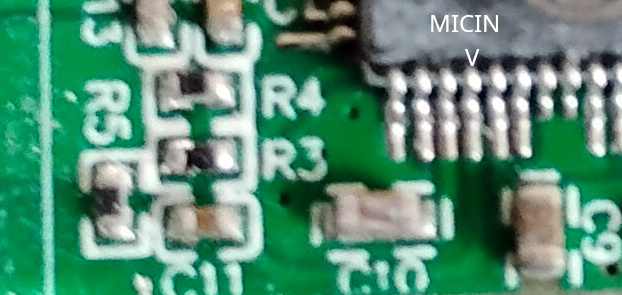
This is the same corner that the other properly numbered image had the bits we wanted. And it is close to the micin pin. If you look closely, you can see the trace from the micin pin goes to C11 and the three resistors R3, R4 and R5 are all on the end of the PCB closest to the cable. I quickly find that the top of R5 and the left of R4 are zero ohms to the tip of the connector. The bottom of R5 and the right of R4 show 8.17ohms. So these are R10 and 12 on our schematic above. After some more measuring I have found out that R3=R11, R4=12 and R5=R10
R4 must be removed.
R4 is gone but leaves behind bits that might short something
All cleaned up and ready to test.
Everything tests out, 3vdc is gone and sound is brighter. Lets put it together
There is a rash on the side where I opened it. Heat shrink tubing would make it look much nicer.