|
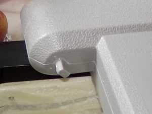
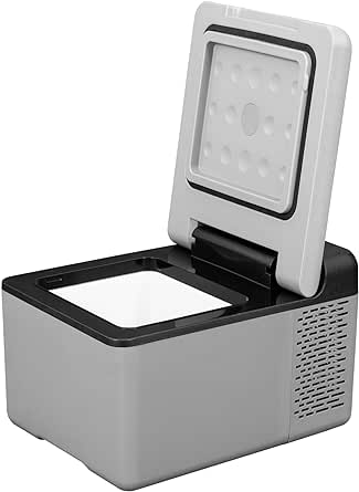
First take the lid off. If the lid is lifted to about 45 degrees up from closed,
a flat screwdriver should be able to force the lid towards the cavity and come right
off.
|
|
|
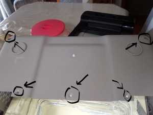
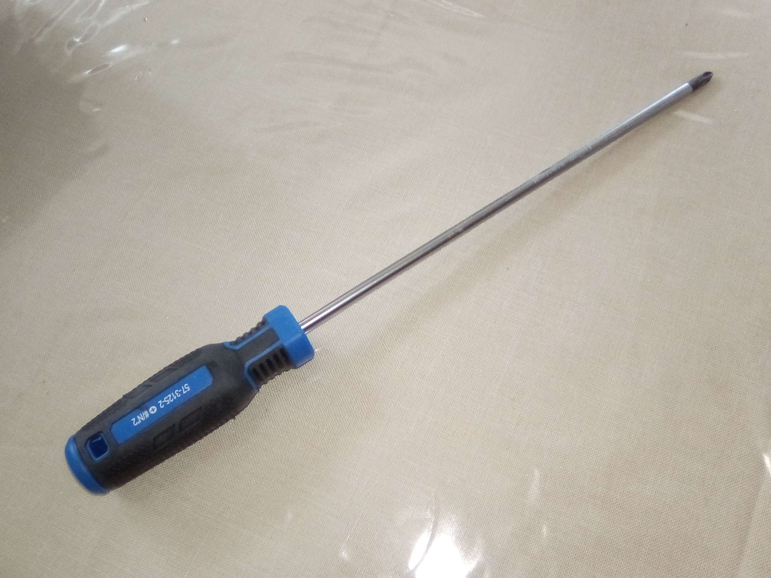
Turning the unit on it's side I found three phillips screws were visible.
I removed those but the vented cover was only loose not removable. There were
two deep holes and when investigated, showed two more phillips screws way
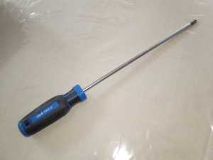
down inside. None of my phillips drivers had a long enough shaft, so
I had to buy one. Now the "works" cover comes off.
|
|
|
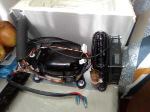
"The works" I want to leave this connected to the case as long as possible.
In my case the included mounting will work really well for mounting the works on the other
side of the bulkhead from the icebox. I will just need to put one hole from the works
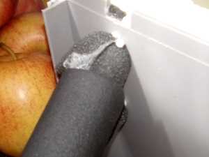
into the icebox through which the chiller "plate" and temperature sensor will go. The original
fridge uses some closed cell foam like pipe insulation (similar to pool noodle) and so I will
use the same to plug the hole as it will allow easy removal for maintenance. |
|
I found the next thing to do was to pry the top black piece off.
I used a flat screwdriver to lift the
edges. There are wires attached to the control panel, so one has to be careful not
to pull the cover off
too hard. |
|
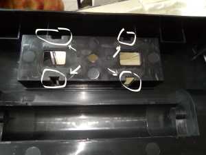
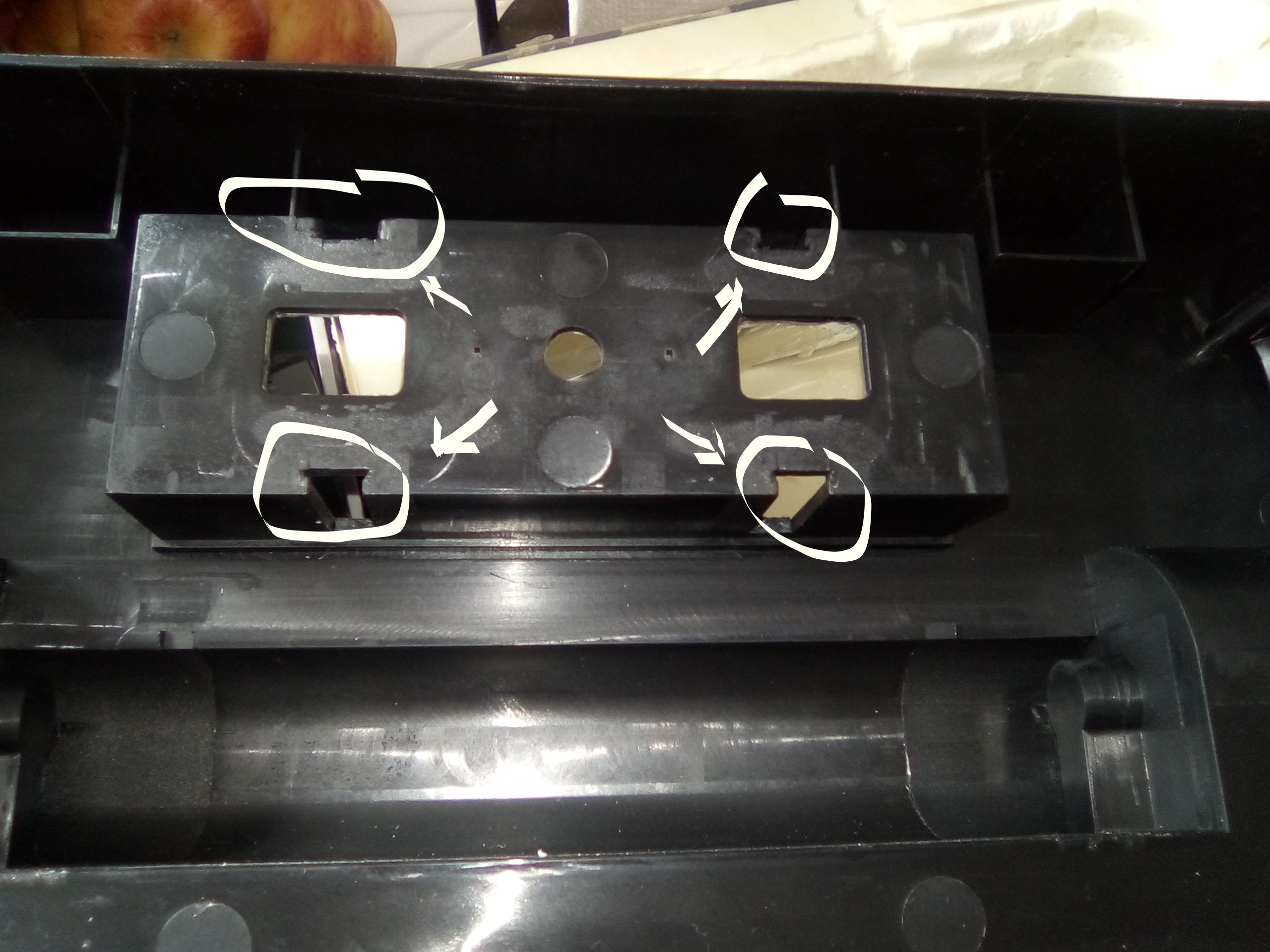
Now it is time to remove the control panel. From the bottom, a flat screwdriver
can be used to
release the four clips that hold the control panel in place. It will be free to
come out the top
of the cover.
|
|
|
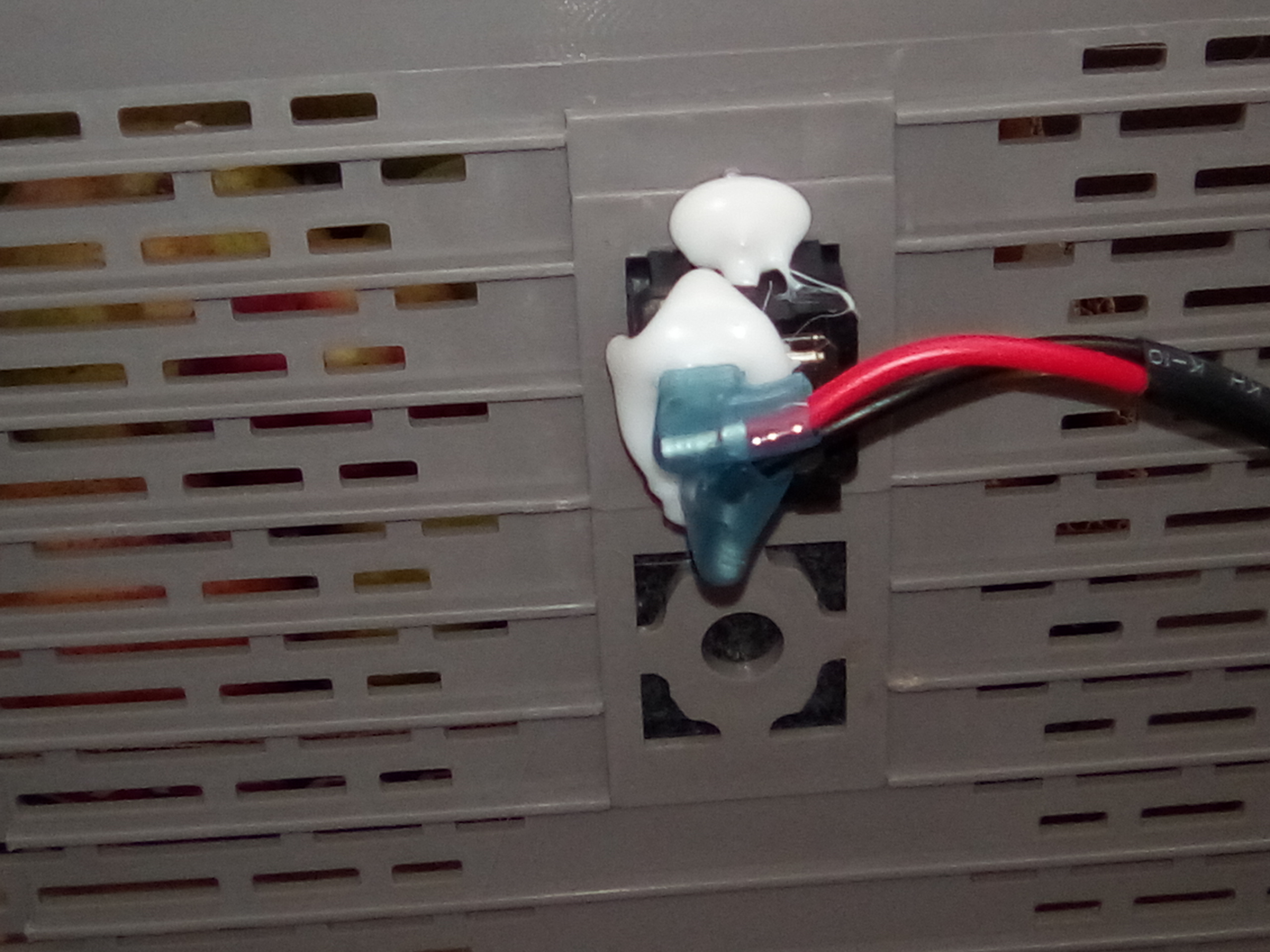
Remember where the two plugs go (or more if you have a different model).
A picture is a good way to remember this.
|
|
|
With the control panel removed, the top cover can be placed aside.
I have saved mine because I may
wish to use part of it as my control panel surround. |
|
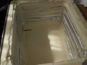
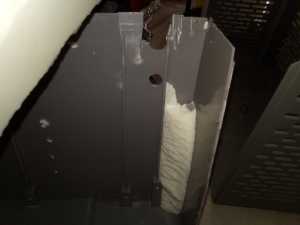
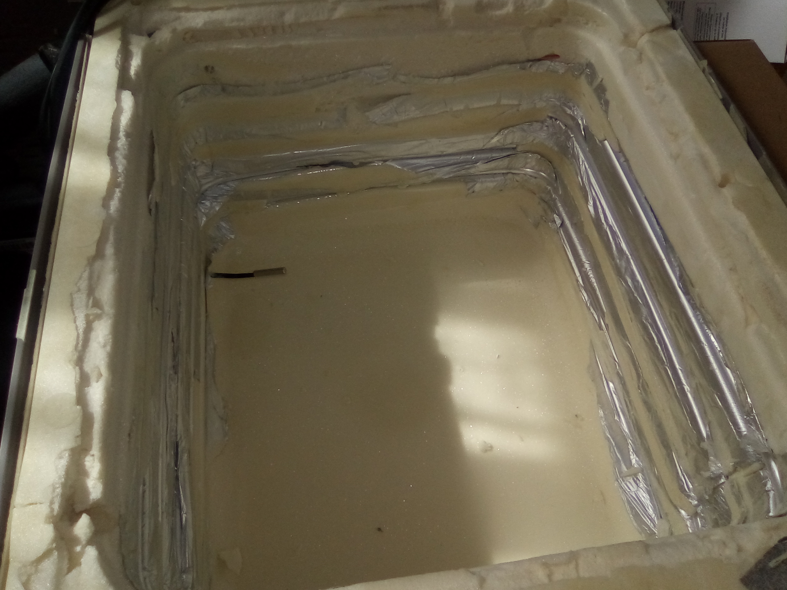
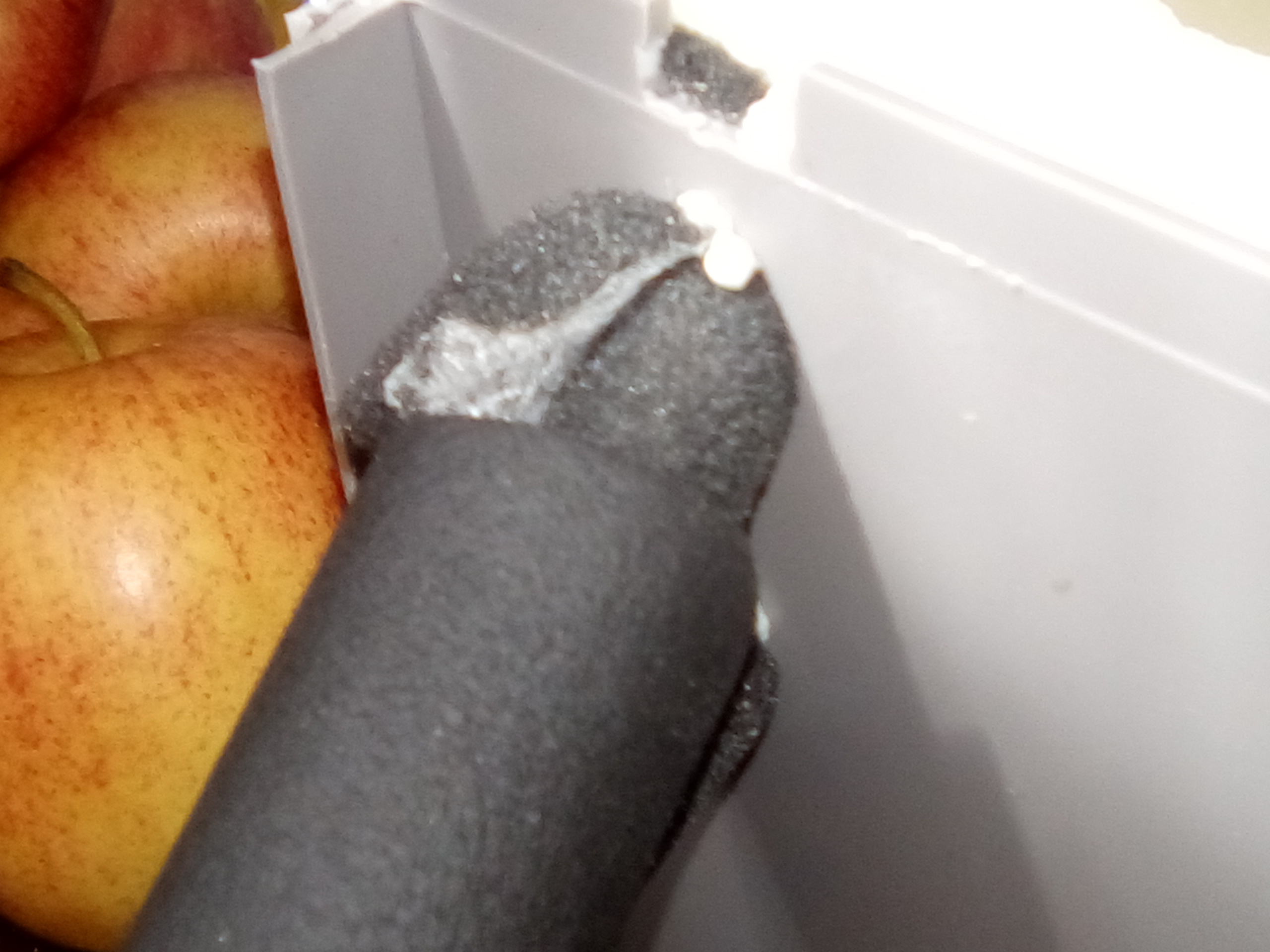
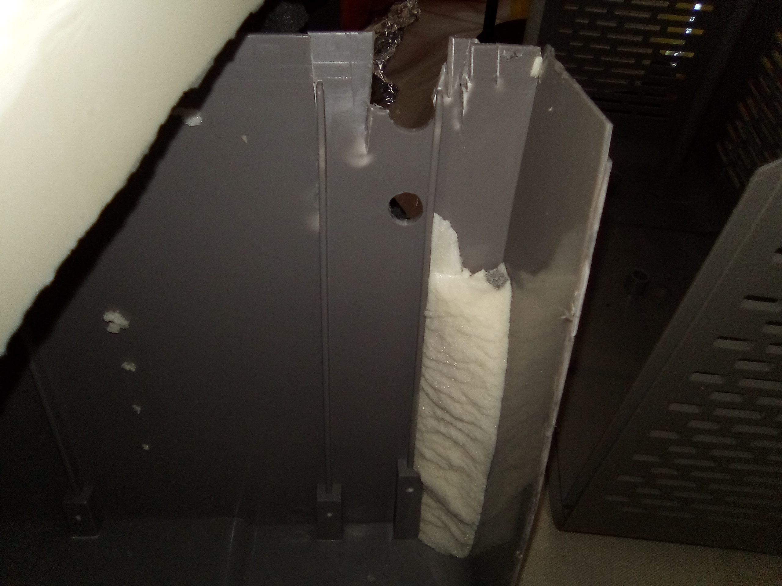
Then I took out the freezer liner. It came out in pieces or strips. Sort of pealed
off the sides.
I found the chiller tube had just been taped on to the outside of the inner liner
so it is stuck into
foam.
|
|
|
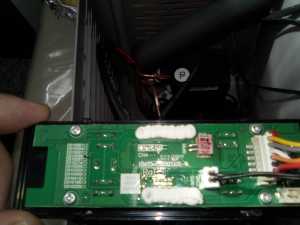
At this point, I hooked up the control panel and tested things to
make sure it still worked. I was
not overly worried about this as even having to buy the equipment to fix a
leak would not equal
the cost of an icebox upgrade kit and even then, the kit install might require
leak fix equipment
anyway. In this case everything still worked. |
|
Next will be removing the outer cover. The temperature probe and the chiller
copper go through
holes in the bottom cover so I have to be careful not to break these.
|
|
|
|
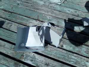
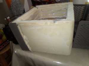
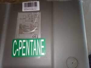
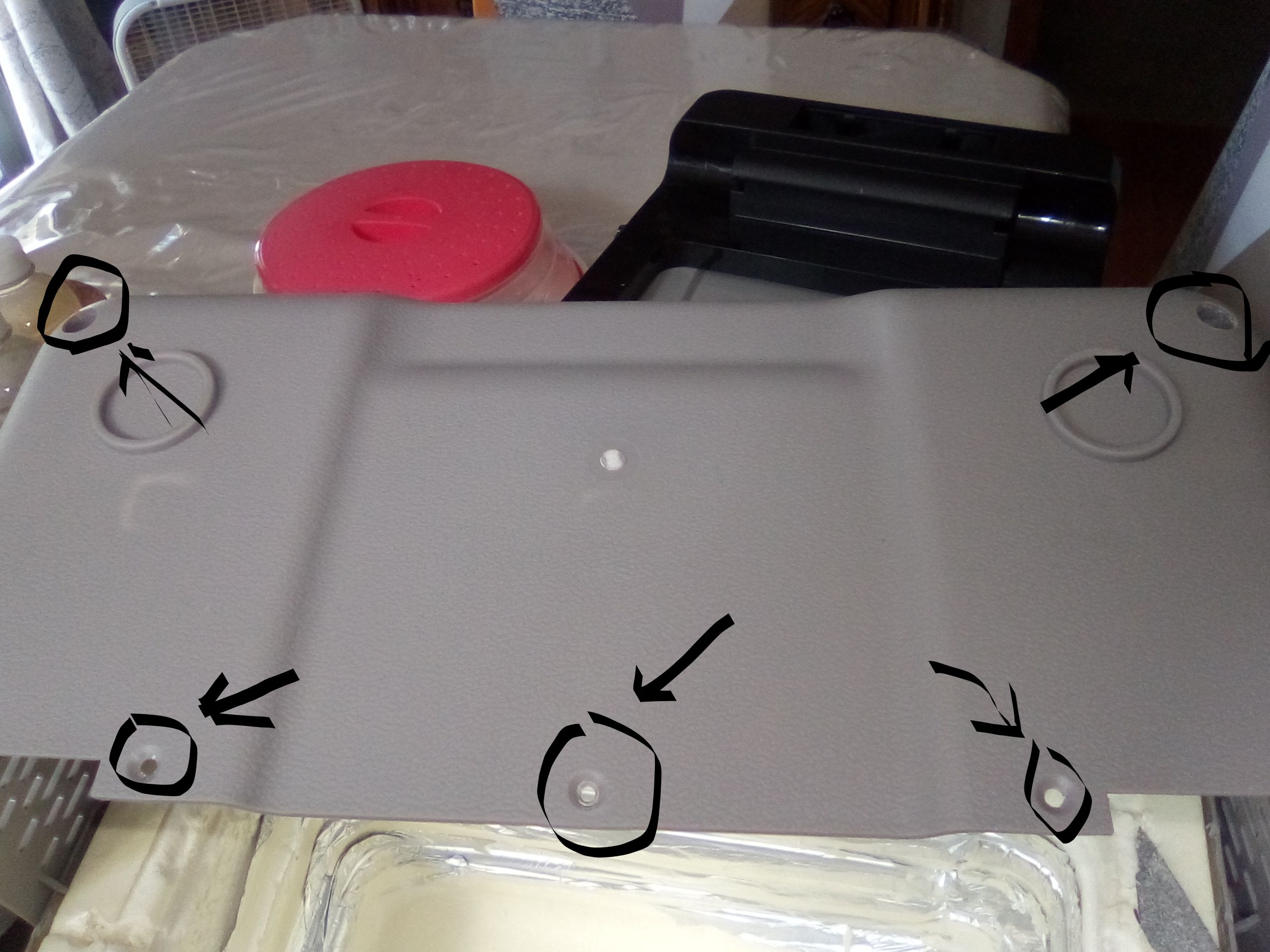
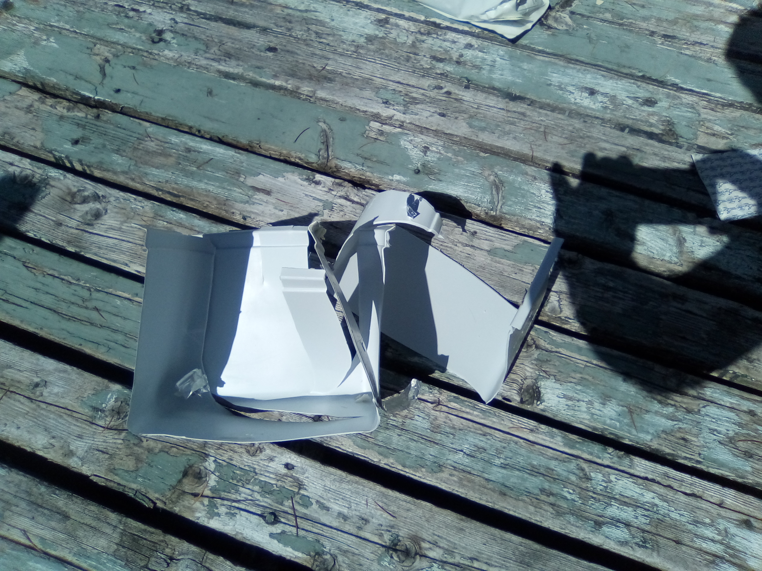
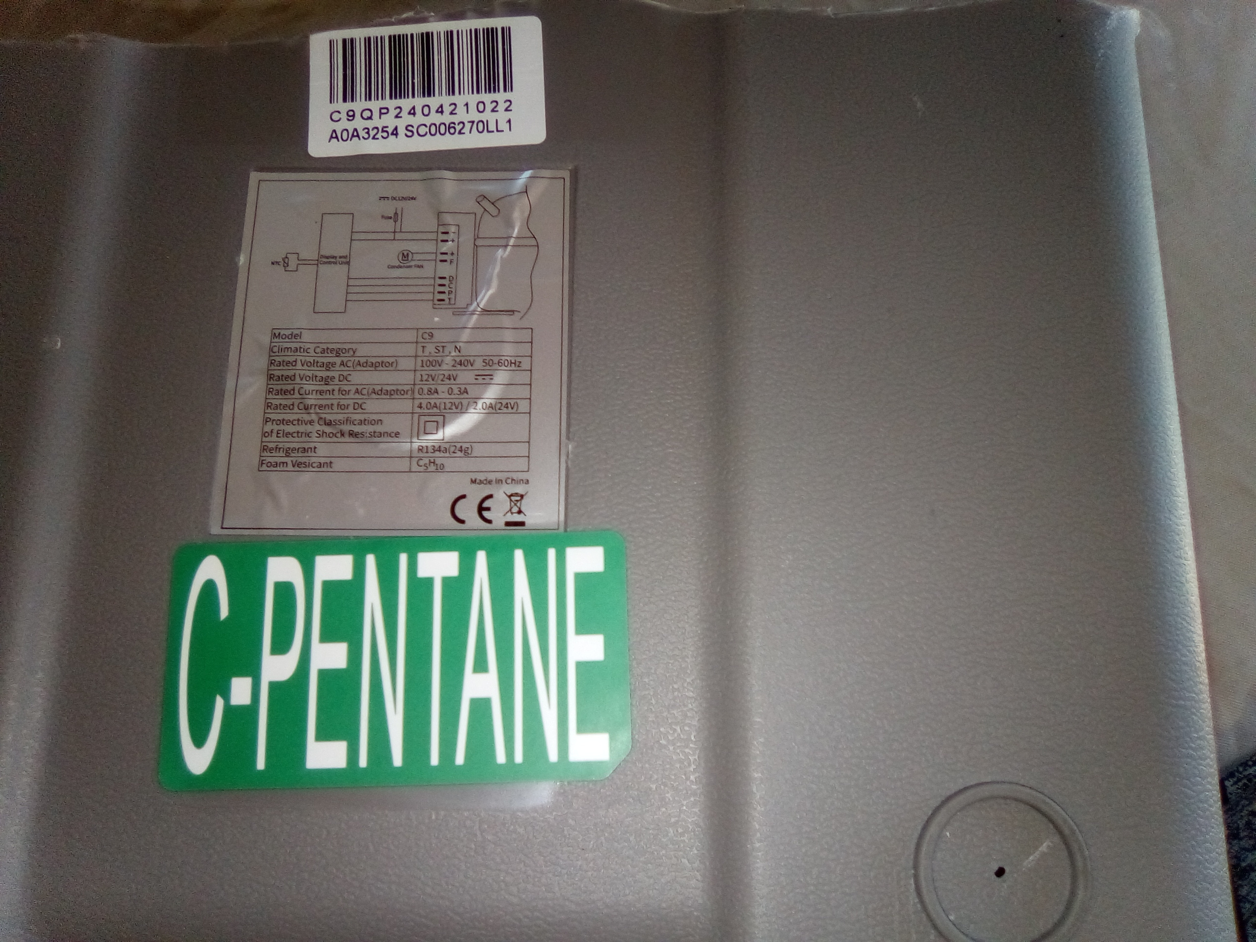
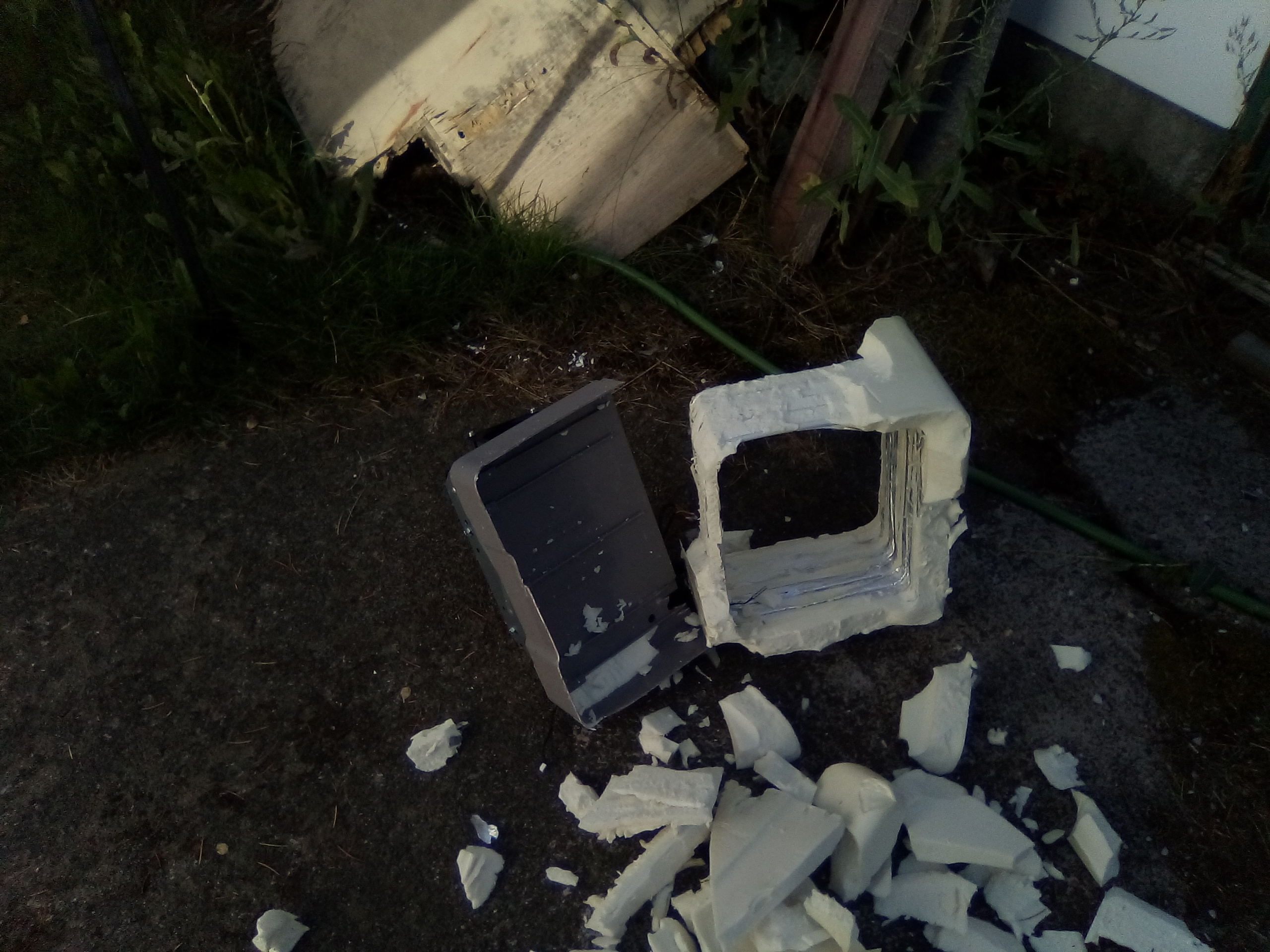
I found tin snips worked just fine to cut most of the case off. Just cut down
both sides and bend across the bottom to make cutting the bottom easier.
The bottom has some interesting info
on it, so save that or take a good picture at least.
|
|
|
|
The snips worked well to cut around the chiller tubes but
the sensor plug came out through the
hole with no cutting required.
|
|
|
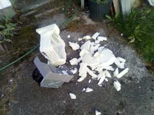
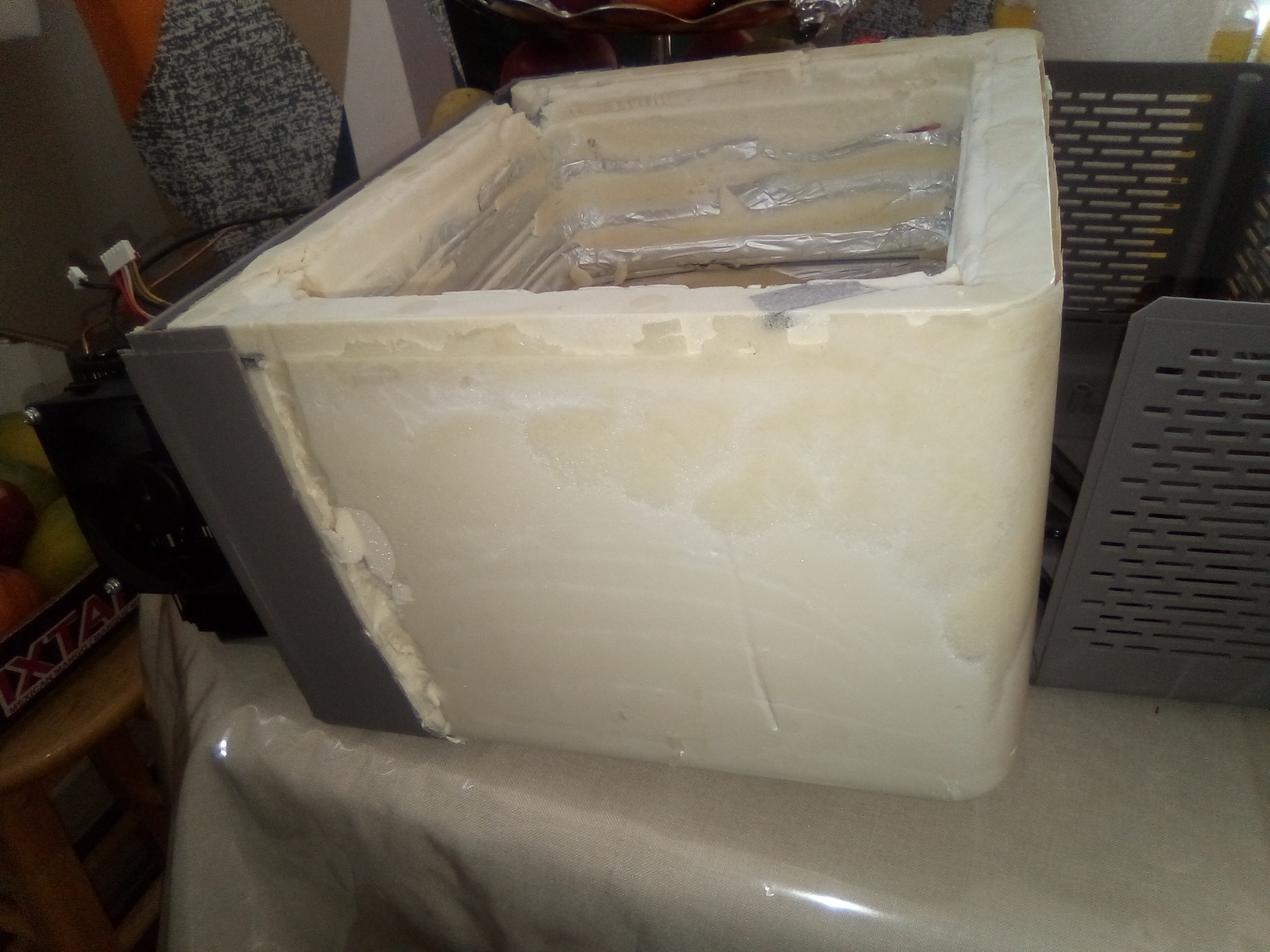
Now, The foam... I was hoping there would be some chemical that
would just melt the foam. The
answer is yes and no. It appears MEK will do so but it is really
unhealthy and even then it is suggested
to remove as much foam as possible using mechanic means. So lets start.
I used a small thin
pry bar for the big bits but found a lot could be done just with fingers.
|

|
|
|
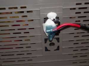
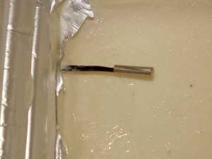
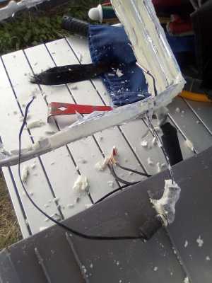
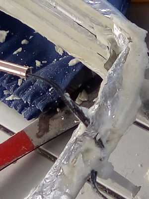
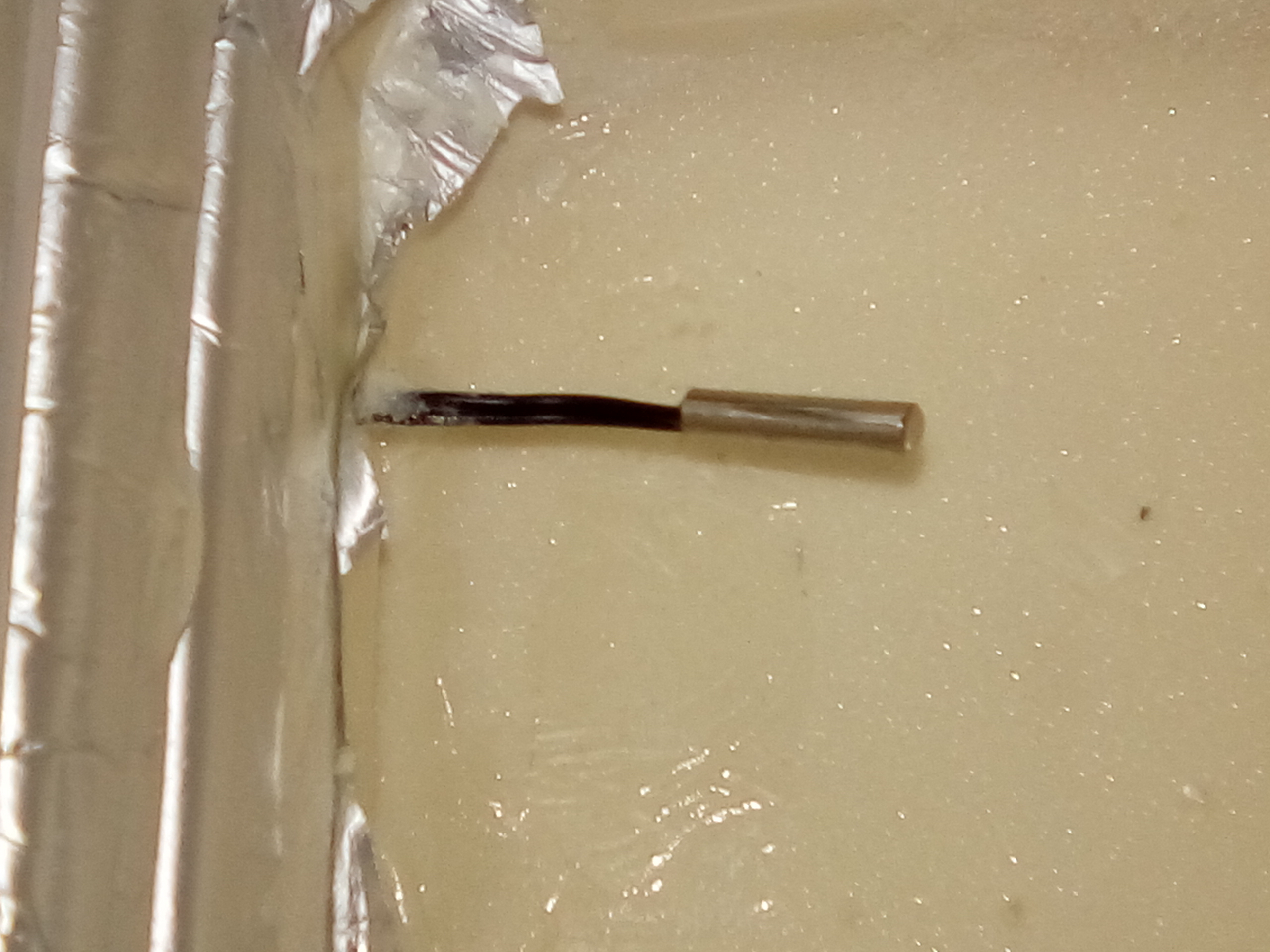
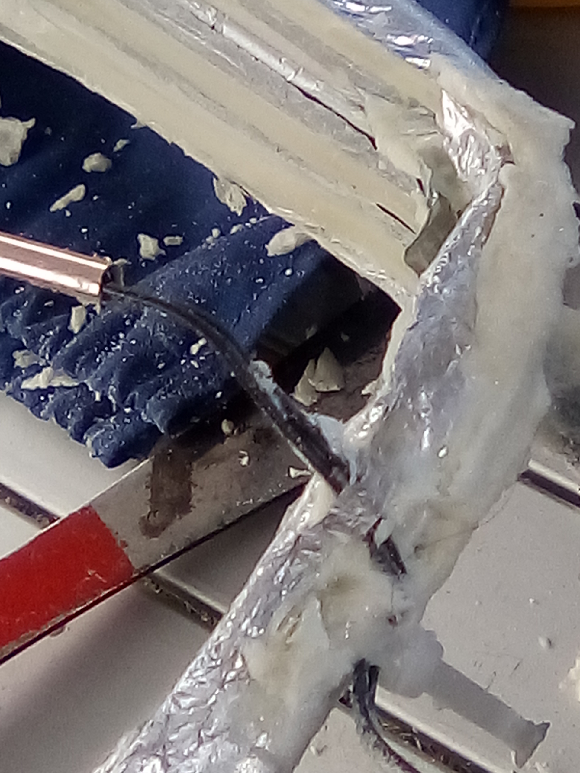
I was careful around the temperature sensor finding a tywrap holding it at the bottom and
a mass of foam mixed with the expanding stuff. I cut the tywrap with care and slowly cut the
lump off with side cutters.
|
|
|
|
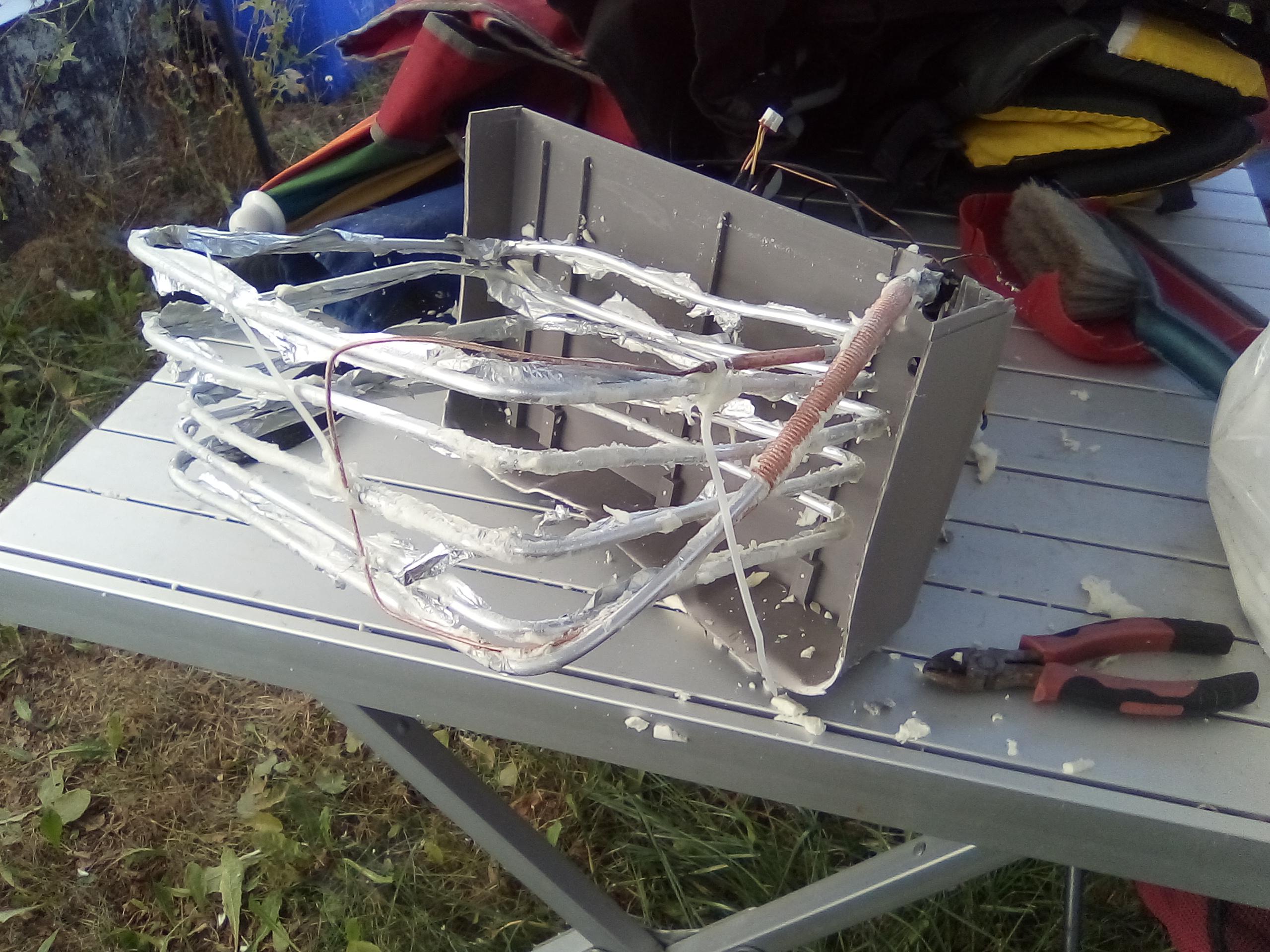
Ok, here is the bit I have to get through a hole into my icebox.
|

|
|
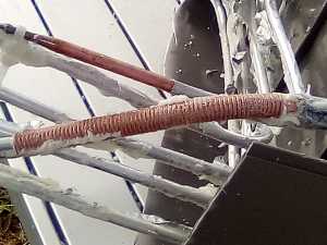
The small tube wraps around the big tube:
|
|
|
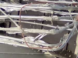
Then loops up to the top gracefully before flaring out to join the large tube.
The large tube gently spirals down, acting as the cooling surface before exiting.
I think the downwards trend is important... but then it does go up to exit...
|
|
|
|
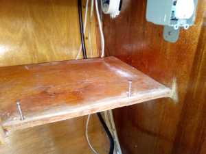
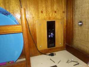
So here we are out at the boat. We see the inside of the icebox after I
have removed the shelf installed by a previous owner. We will reinstall it
after cooling radiator is in. The top left shows an unused speaker that will
be removed so the control panel will fit.
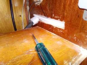
The second picture shows the shelf behind the bulkhead to the left of the
icebox. The speaker back can be seen at the top. The compressor rack will be mounted
under the shelf to the bulkhead.
|

|
|
|
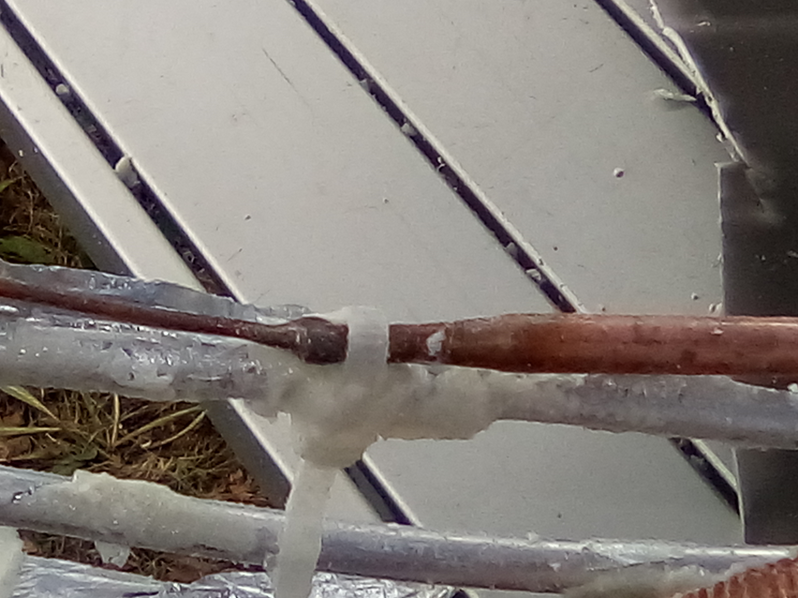
Note that the shelf is lower than the counter top. The slot for the coil to fit
through will be above the shelf as high on the inside of the ice box as possible.
The slot has been cut. The coils were squeezed together and pushed through
and the temperature probe goes through the top of the slot. The cables to the control panel
can just be made out to the left of the slot which has been filled with foam for insulation.
|

|
|
|
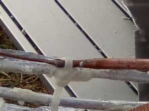
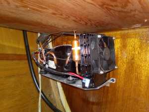
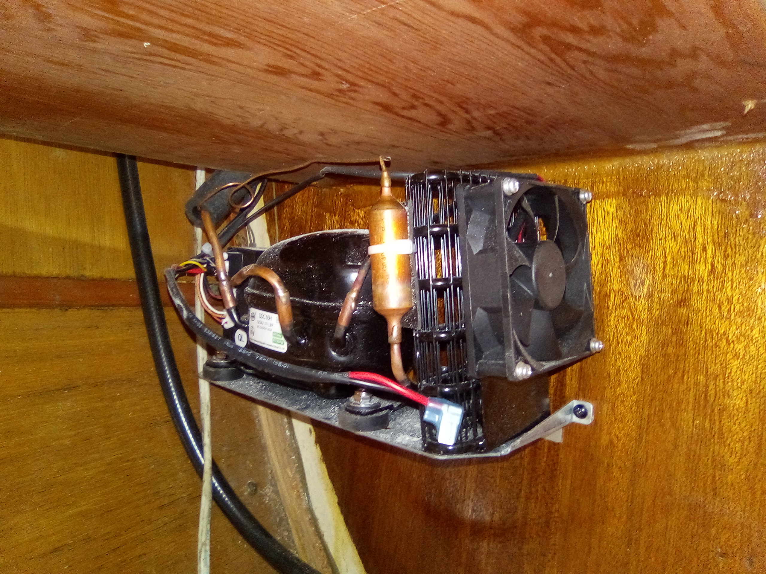
On the right is the coil after being pushed through the slot. It went through
quite easily. The shelf was reinstalled and the temperature probe is hanging
in front of the shelf. Under the shelf on the other side of the bulkhead,
the compressor is installed. It will be completely hidden behind the small
fireplace/heater that goes in front of the shelf.
|
|
|
|
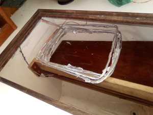
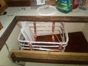
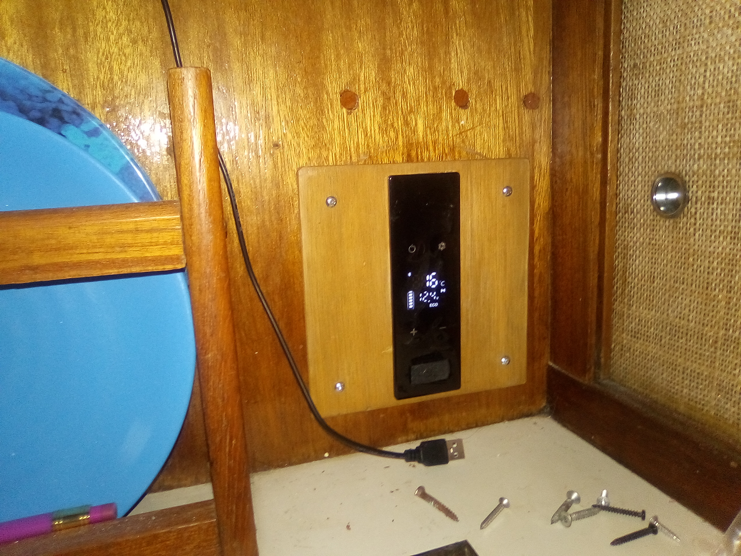
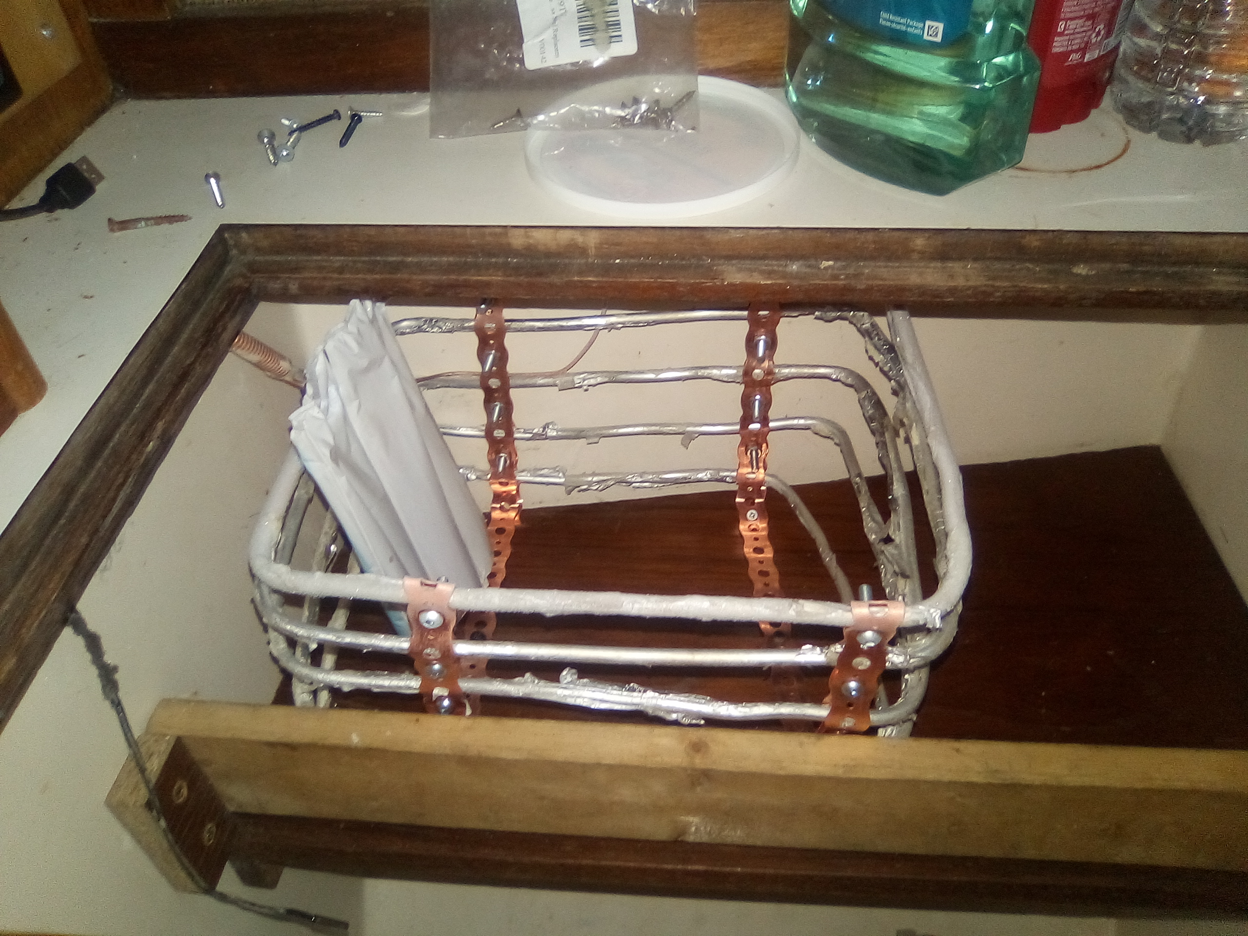
A few days later I had made a cover plate for the round hole for the control panel
to fit in. It looks quite good I used some copper strips as a clamp to hold the
coils in place and to fasten them down to the shelf. There are some freezies in there
already. The screws are too long and I have cut a few of them off but it is too hard to
get at the rest of the screws with tool (a saw) I had available. I need my mini drill
with a cut off disk to finish that
|
|
|
|
So, whats next? It is almost finished, everything works. I may put a metal shield
around the coil so that can act as a mini freezer. It would also make the install look
more finished. The temperature sensor should get taped to the side or maybe even extended
so it can reach the bottom. I think it might also help save on battery if I insulated the
top of the icebox and cover. While the compressor is hidden from view, I may still
put some foam around it to make it quieter. I would still have to leave it open
at both ends for heat evacuation but most of the noise is from the compressor not
the fan.
|


